How to Test an Oxygen Sensor (P0420)
(This testing applies to 4-wire Heated Oxygen Sensors only, not wide-band or A/F ratio sensors.)
What are the symptoms of a bad oxygen sensor?
- Check engine light
- Lean running engine
- Rich running engine
- Excessive exhaust smell
- Poor fuel economy
- Catalytic converter failure
Recommended Tools
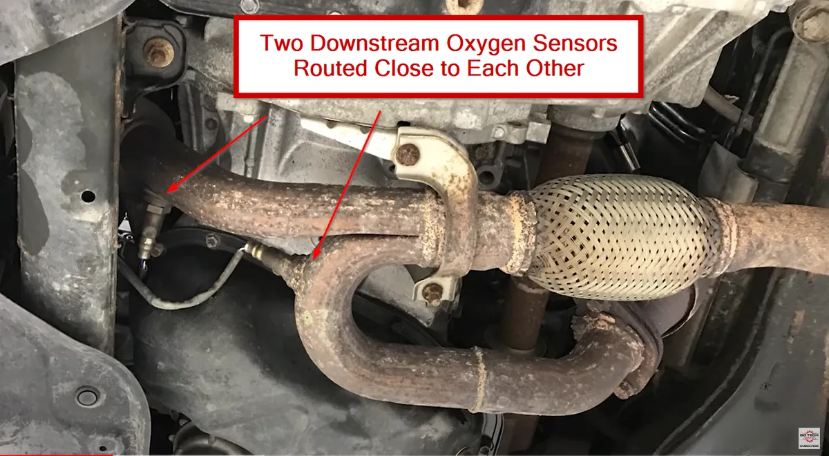
Locate the correct oxygen sensor for testing
- Whether diagnosing a trouble code or testing function, first locate the correct/suspect sensor.
- Determine if it’s Bank 1 (cylinder #1 side) or Bank 2, and whether it’s upstream (before catalytic converter) or downstream (after converter).
- Use the Firing Order Database to confirm the cylinder layout and bank orientation.
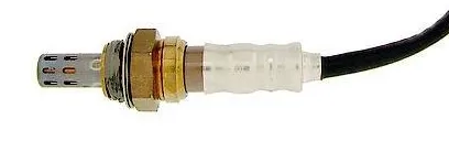
Visual inspection
Difficulty: 1/5
Time: ~10 minutes
Tools required: Flashlight, inspection mirror
- Check for damaged wiring, loose connectors, or contact with hot exhaust components.
- Confirm the sensor is securely installed in the exhaust stream.
Test the oxygen sensor heater
Difficulty: 2/5
Time: 30–60 minutes
Tools required: Flashlight, multimeter
- Identify the two heater wires—on most 4-wire sensors, these are same-colored.
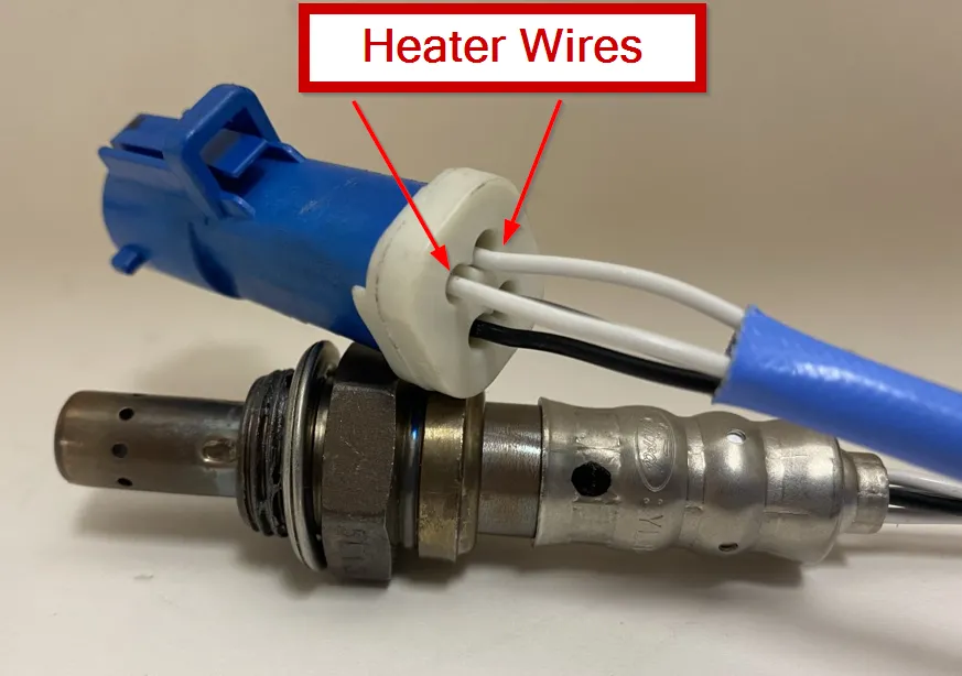
- Using a multimeter set to Ohms, measure resistance between the heater pins.
- Typical range: 4–25 Ω (consult service info).
- If resistance is out of range, replace the O2 sensor.
Suggested Tools:
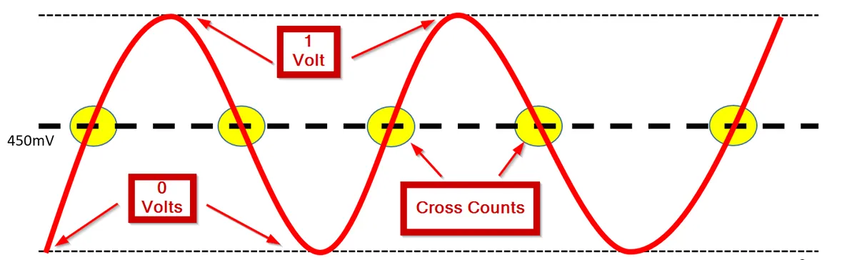
Check the oxygen sensor signal
Difficulty: 3/5
Time: 30–60 minutes
Tools required: Multimeter or scan tool
- Warm the engine to operating temperature.
- Monitor O₂ voltage range (0–1.0 V typical).
- Upstream (S1) should switch rapidly above and below 450 mV.
- Downstream (S2) should fluctuate slowly and average between 500–700 mV.
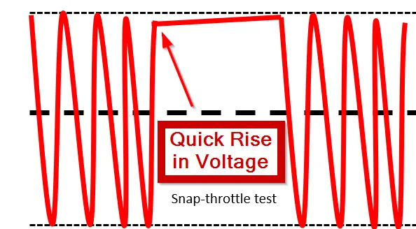
Test the oxygen sensor signal range
Difficulty: 3/5
Time: 30–60 minutes
Tools required: Multimeter or scan tool
- Verify the O₂ sensor can read lean (< 450 mV) and rich (> 450 mV).
- Create a small vacuum leak to induce a lean signal — voltage should drop quickly.
- Perform a snap-throttle to create a rich condition — voltage should spike high.
Helpful Tool:
Live Data Scan Tool
Replace an oxygen sensor
Difficulty: 2/5
Time: 30–60 minutes
Tools required: O₂ socket or 7/8" wrench
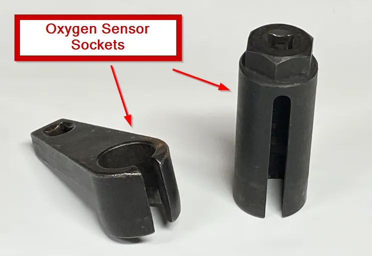
- Disconnect the electrical connector and remove the sensor with an O₂ socket.
- Apply anti-seize if recommended and torque to spec.
- Reconnect harness and clear any stored codes.
Suggested Replacement Sensors:
Oxygen Sensor FAQ
How should an upstream (S1) sensor behave at idle?
It should switch rapidly above and below ~450 mV when the engine is at operating temp.
What’s normal heater resistance?
Typically 4–25 Ω (always verify the exact spec for the vehicle).
Can a bad catalytic converter mimic a bad O₂ sensor?
Yes. A failing cat often makes the downstream sensor switch actively like the upstream sensor.
Upstream vs downstream—what’s the difference?
Upstream (before the cat) reacts quickly to mixture changes; downstream (after the cat) is slower and averages ~500–700 mV during steady cruise.
Is it safe to induce a vacuum leak for testing?
A small, brief leak for testing is fine—watch for a quick drop below 450 mV—then restore the hose immediately.